As previously discussed, most modern sine wave inverters employ a voltage source topology and are referred to as voltage source inverters (VSI). Depending on the type of feedback and control scheme that is employed, the VSI topology can be used to implement inverter solutions for a wide variety of applications, including motor drives, grid-tie, and AFE/active rectifiers, as well as Voltage Mode Inverters (VMI).
VMI’s are also referred to as stand-alone or off-grid inverters. They are designed for remote stand-alone applications or off-grid power systems with battery backup where the inverter draws its DC power from batteries charged by some other power source, such as a PV array. Applications for VMIs include solar home systems, rural electrification, and village electrification in remote areas where the utility grid is not available.
An uninterruptible power supply, or UPS, is another application for VMIs. UPS’ are generally designed to provide emergency power to a load when the input power source, typically the grid, fails. In UPS applications the VMI provides near-instantaneous protection from input AC power interruptions, by supplying energy stored in batteries or a flywheel.
Yet another application for VMIs is in frequency conversion. The VMI can be used to convert from one AC frequency to another. For example, aircraft are designed to operate off of 120V, 400Hz AC power as opposed to the typical 60Hz utility power. A VMI frequency converter would typically rectify 60 Hz utility power on its input to create a DC “link” voltage. The VMI controller would then create and regulate a 400Hz output voltage for use by the aircraft.
Control Topology
While there are several different types of control schemes used in VMI implementations, ultimately they all provide control of the fundamental voltage magnitude and frequency of the AC output voltage. The figure below illustrates the typical VMI control topology for a single-phase inverter. The block diagram can easily be extended to a three-phase system.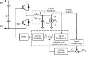
In a VMI controller, the voltage reference, Vref, is used to set the desired output voltage frequency and amplitude. The circuitry is used to measure the actual output voltage, Vo, and calculate the error between the reference and the output. A variety of control laws can then be used to correct the error. In some systems, the output of the voltage controller is directly used to compute the PWM commands. In these systems, additional features are provided to limit output current during abnormal operating conditions. In a multi-loop architecture, as illustrated in this block diagram, the output of the “outer” voltage control loop serves as a current command to an “inner” current controller. One of the benefits of the inner current control loop is that it inherently provides current limiting by clamping the output of the voltage controller to the desired current limit value.
This discussion of the VMI is part two in a series of blog posts about inverters. In future posts, we’ll discuss specific applications, including grid-tie, AFE/active rectifier, VMI/stand-alone and motor drive inverters, as well as the different control techniques commonly employed.