This post is first in a series discussing the subsystems and key components that go into a grid-tie inverter (GTI), and design considerations for the development of a practical commercial system. The majority of topics will apply equally to active front-ends (AFEs), and active rectifiers (more on the subtle differences between these two is covered in Active Front-end or Grid Tie Inverter?). We’ll use the term GTI in a general sense for this series, and point out differences between AFEs and active rectifiers when relevant.
Before delving into the details, let’s first examine what a GTI is by comparing it to the more familiar voltage mode inverter (VMI). A VMI is a DC to AC converter. It generally is intended to source power into a load and thus has a low output impedance to maintain a stable output voltage with varying loads. A GTI is also a DC to AC converter, but it is generally intended to source power into a low impedance utility grid, so its output impedance is therefore high. Addressing these dissimilar operating characteristics requires a different output filter topology, a different control loop implementation, and a different reference implementation. Secondary requirements that arise from things like startup and fault handling impose further distinctions between the two, which we will explore later on.
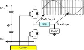
The voltage source PWM inverter power stage, typically used for both VMI and GTI applications, inherently produces a low output impedance. For the VMI, an LC filter is typically employed to convert the low impedance, pulsating power stage waveform, to a low impedance, continuous waveform. One of the key attributes of the LC filter is that it has a high input and a low output impedance. In general, we always want to couple low impedance nodes to high impedance nodes. Coupling two low impedance nodes together result in wildly varying currents, and coupling two high impedance nodes together results in wildly varying voltages. This is an important consideration in our modifications for GTI operation, as well as for the architecture of multi-converter systems that address more complex requirements.
We make two key modifications from the VMI configuration, shown below, to raise its output impedance.
First, we replace the LC output filter with an LCL. The second inductor, which connects to the grid, produces an output impedance that increases with frequency. Then, using a current measurement signal taken from the inverter’s output, we implement a current control loop. This actively increases grid connection impedance at low to mid frequencies, where the added inductor’s impedance is still relatively low. Now, all we have to do is synchronize the modulation to the AC line, which is typically accomplished with a phase-locked loop (PLL) reference generator. The net result is an inverter with a controllable output current rather than a controllable output voltage.
One last thing worth considering – while both the VMI and GTI are usually thought of as DC to AC converters, there’s nothing that inherently prevents common topologies from functioning as AC to DC converters. Of course, there aren’t many practical applications for VMI AC to DC conversion, but there are many for the GTI. When configured for AC to DC conversion, they are usually thought of more as AFEs or active rectifiers. There typically are differences in how the control loops are configured for this mode of operation, but the interesting thing here is that most VMIs and GTIs are fundamentally bidirectional converters. This broadens application possibilities considerably.