A general rule of thumb when driving SCRs is to use as short a cable as possible in order to provide the most efficient turn-on characteristics. As cable length increases, two important parameters are degraded: inductance and series resistance.
In order to minimize inductance, gate drive cables should be constructed in a manner that tightly couples, preferably with a twisted pair, the gate and cathode connections. However, regardless of the construction technique, increased cable length results in increased inductance, which in turn slows the rise time, di/dt, of the gate drive current pulses. The second concern when lengthening cables is the associated increase in series resistance which reduces the peak current, IGM, delivered to the SCR gate.
The magnitude of the gate drive current IGM, as well as its di/dt rise time, directly affect key SCR performance characteristics, including:
• Turn-on Delay
• Turn-on fall time of the anode voltage
• Turn-on switching losses
• di/dt of the anode current
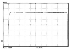
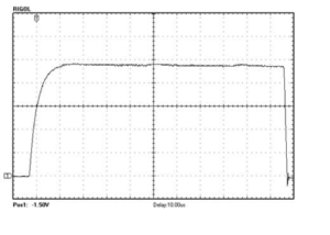
High IGM, typically >2Amps, and rise times of > 2Amp/sec help ensure reliable and efficient triggering of SCR power devices. We recently tested OZSCR1000 and OZSCR1100 gate drive performance using a variety of cables and cable lengths. The following figure illustrates the gate drive current pulse waveform when driven with a 13.5″ cable, (500mA/div, 2usec/div). The second figure illustrates the current pulse waveform when driven with a 150″ cable, (500mA/div, 2usec/div). From these scope plots, the effects of both inductance and resistance are obvious by the increased rise time and reduced current level in the second plot. Please reference Oztek Application note AN-0001 for more detailed test results.