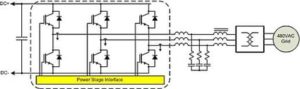
A common question we field regarding grid-tie inverters goes something like “Can I interface to a 480V grid with a 680V DC-Link?”. To answer this question, lets consider a typical Grid Tie Inverter or Active Front End application as illustrated in the figure below.
Generally, our application code uses center-aligned, space vector pulse width modulation (SVM) techniques for maximum DC-Link voltage utilization. Using SVM, the switch-mode AC voltage output of the inverter, before the filter components, is limited by the dead-time of the power stage and any minimum pulse requirements of the IGBT drivers. For example, 3usec of dead-time when switching at 10kHz results in a maximum achievable duty-cyle of 97%. Depending on the switching frequency, these hardware limitations will set the maximum, peak, the line to line output voltage to ~95% to 97% of the DC Link. Note, however, that this is the point at which the duty cycle is clamped, and the controls become non-linear. In practice, you will want to allow several percent duty-cycle for control headroom in order to provide the controller linear operating range. As such, 92-94% is a more practical design value.
The previous discussion addresses the maximum obtainable voltage at the output of the IGBTs. Considering a GTI or AFE converter can source current into the grid, one also has to allow for voltage drops across the filter components at maximum output current. Let’s consider a typical 100kW Grid Tie Inverter interfacing to a 480V AC line. At 10% high line, the maximum peak line voltage is 480*1.1*SQRT(2) = 747Vpk. Assuming 30Vpk is dropped across the filter components, the required minimum DC-Link voltage is given by (747+30)/0.92 = 845V.